CSE668
Lecture
Slides
Spring
2011
2.
3-D
Imaging
Models
Required reading: Sonka Ch 9.
Recommended:
Trucco Ch 9.
Part I of this
course, on
early
vision, is concerned
with the most
basic
vision tasks, such as determining
the depth of a given image feature from the camera, or
estimating egomotion (camera self-motion). Part II,
on late vision, covers the more complex vision
tasks, those which build on early vision
capabilities (eg. tracking, object recogntion). Part
I will take us up to the midterm exam.
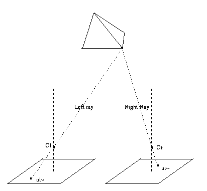
We first consider the traditional passive vision
approach, and then the more recent active vision
approach to early vision.
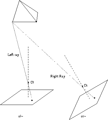
CSE668 Sp2011 Peter Scott 02-00
Passive early vision
3-D Imaging models
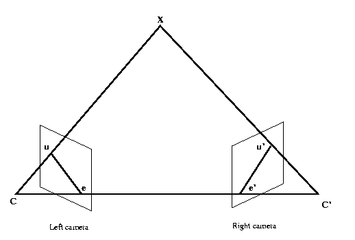
In passive vision analysis, we work closely with our
imaging
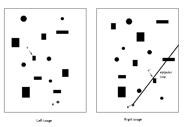
system's
imaging model, that is, its
quantitative
mapping from
3-D scenes to
2-D images. Then the main job
can be
undertaken: to
invert the imaging model, that
is, recover the
3-D scene. Recall that Passive Vision
is synonymous
with Vision as Recovery.
CSE668 Sp2011 Peter Scott 02-01
Camera
model
In order to have a quantitative description of how
a given camera views the real world, we need a camera
model. This is a mapping C: R3->R2 which specifies
how the 3D scene will appear on the 2D image plane of
the camera. A camera model supports two types of
parameters:
Intrinsic parameters: properties of the camera
itself, which do not change as the position and
orientation
of
the
camera
in
space are changed.
Extrinisic parameters: those which change with
position
and
orientation
of
the
camera.
CSE668 Sp2011 Peter Scott 02-02
Eg: focal length and lens magnification factor are
intrinsic parameters, focal point location and
vector orientation of the optical axis are
extrinsic
parameters.
Both sets of parameters must be completely specified
before the camera model C: R3->R2 is known and we can
predict the 2D image on the image plane that derives
from any given
3D scene.
CSE668 Sp2011 Peter Scott 02-03
Perspective
projection
The geometry of perspective projection is used to
develop the
camera model.
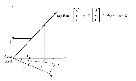
Define a ray as a half-line beginning at the origin.
CSE668 Sp2011 Peter Scott 02-04
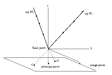
All points on a given ray R will map into the
single point r in the image plane. The set of
all such mappings is the perspective projection.
CSE668 Sp2011 Peter Scott 02-05
Formally, let x and x' be nonzero vectors in Rn+1
(we will use n=2) and define x == x' (x is
equivalent to x') if and only if x'=αx for some
scalar α not equal to zero. Then the quotient
space of this equivalence relation (set of
equivalence classes) is Pn, the projective space
associated with
the Euclidean space Rn+1. Note
that for the
projective space is lower-dimensional
than the
Euclidean space (dim = 2 vs 3).
CSE668 Sp2011 Peter Scott 02-06
Informally, points in P2 can be thought of,
and represented, as follows. Take a point in R3,
say [x y z]T, write as z [ x/z y/z 1]T (z~=0).
Then [x y z]T in R3 maps into the point
r = [x/z y/z]
in
P2.
Eg: [30 15 5]T -> [6 3]T
[ 3 3/2 1/2]T -> [6 3]T
So these two points in R3 project to the
same
point
[6
3]
in
the projective space P2.
CSE668 Sp2011 Peter Scott 02-07
The
pinhole
(single
perspective)
camera
model
This is the simplest possible lensless camera model.
Conceptually,
all light passes through a vanishingly
small pinhole
at the origin and illuminates
an image
plane beneath
it. The geometry here will be quite
simple. Most of
the work in
understanding the model
will be in
keeping several
distinct coordinate
systems
straight.
CSE668 Sp2011 Peter Scott 02-08
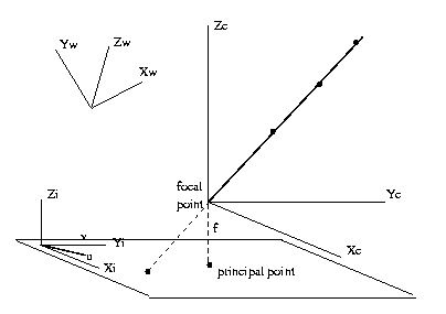
(Xw,Yw,Zw):
World
coordinates.
Origin
at
some
arbitrary
scene
point in R3.
(Xc,Yc,Zc):
Camera
coordinates.
Origin
at
the
focal
point
in R3.
(Xi,Yi,Zi):
Image
coordinates.
Origin
in
the
image
plane,
axes
aligned with camera coordinate
axes.
(u,v,w): Image
affine coordinates. Same origin as
image
coordinates
but u and Xi axes may
not
coincide
(others do coincide), and
there
may
be a scaling.
CSE668 Sp2011 Peter Scott 02-09
Recall that the camera model is a mapping C:R3->R2
which takes us from world 3D coordinates to (u,v)
image affine coordinates. We will develop the
camera model in
three steps:
Step 1. (xw,yw,zw)->(xc,yc,zc) world to camera coords.
These two 3D Euclidean coordinate systems differ by
a translation
of
the origin, and a rotation in R3, ie
by an affine
transformation.
CSE668 Sp2011 02-10
This
coordinate
transformation
is
given
by
Xc = R(Xw-t)
where Xw = [xw yw zw]T is a 3D point expressed
in world coordinates;
Xc = [xc yc zc]T is the same point in
camera coordinates;
R is the 3x3 rotation matrix (pitch,
roll, yaw);
t is the translation vector (origin of
camera coordinates expressed in world
coordinates).
Note that R and t are extrinsic parameters of the
camera model, since they change with change of
camera location
(t) and orientation (R).
CSE668 Sp2011 02-11
Step
2:
Project
the
point
in
camera coordinates
onto the image plane, keeping camera coordinates.
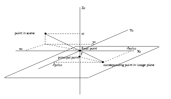
The coordinates
of the corresponding point in the image
plane,
retaining
camera coordinates, are
Uc = [-fxc/zc -fyc/zc
-f]T
CSE668 Sp2011 02-12
Step
3:
Uc->(u,v), the
image affine coordinates in the
image
plane.
The
image
affine
coordinates are
related
to
the
Uc
camera
coordinates projected onto
the
image plane [-fxc/zc
-fyc/zc]T by a further
translation
shear
of
respect
[u v]T
= S [-fxc/zc -fyc/zc]T
- [u0 v0]T
where
[u
v]T = final image affine coords in the
image
plane
S
=
2x2
matrix
of
form [a b; 0 c]
[u0 v0]T = principal point expressed in
image
affine
coordinates.
CSE668 Sp2011 02-13
The
S-matrix represents the scaling (a,c) and shear of
the x-axis (b).
The vector [u0 v0]T is the
translation
of the origin
between the Euclidean image coordinates
and the affine
image coordinates in R2.
This set of
results can be
expressed in a compact way using
homogeneous
coordinates. These are
coordinate vectors whose
last
[u v 1] = [
a b -u0;
0
c
-v0;
0
0
1][-fxc/zc
-fyc/zc 1]T
=
[-fa -fb
-u0;
0
-fc
-v0;
0
0
1] [xc/zc yc/zc
1]T
which agrees
with the translation, scaling and shear coord
transformation
equation of the preceeding slide.
Designating the
3x3 matrix as K, the camera calibration
matrix and
multiplying
by zc we get
zc [u v 1]T = K [xc yc zc]T
CSE668 Sp2011 02-14
Note
that
the
the
camera
calibration
matrix K contains the
intrinsic
parameters of the camera model, those that do
not change as
we
relocate and reorient the camera.
So putting the
pieces from Step 1 and Step 3 together,
zc [u v 1]T = K [xc yc zc]T
and recalling
the relationship between camera and world coords:
Pinhole
camera model:
zc [u v 1]T
= K R ([xw yw zw]T
- t)
The completes
the camera model PCM, which maps points from
world
coordinates [xw yw
zw]T in R3
to image
coordinates [u v]T
in R2.
To use the PCM, we must know both
(R, t) and the
intrinsic parameters (K). Then for any input
world point [xw
yw
zw]T we
plug in to the right hand
side,
and
after
evaluating the RHS, convert the result to
homogeneous
coordinates by
factoring out the value of the last (third)
coord to get
the desired form zc[u v 1]T.
CSE668 Sp2011 02-15
Eg: Extrinsic parameters: Assume the camera
coordinates represent a +30 degree cw
rotation in the xy plane relative to the
world coordinates, and that the origin of
the world coordinate system is located at
[2
2
0]T in camera coords.
Intrinsic: f=4, the image coords (u,v)
are both scaled by 2 relative to the
camera coords, there is no shear, and
the image affine coord origin is at the
principal
point
of
the
camera.
Find the (u,v) location of the world point
[9 3 3]T and the ray that maps to that
point.
CSE668 Sp2011 02-16
Extrinsic:
R = [cos30 sin30 0;-sin30 cos30 0; 0 0 1]
=
[.866 .5 0; -.5
.866 0; 0 0 1];
Note: the lighter font weight indicates Matlab notation
t : Xc = R(Xw-t)
since Xw=[0 0 0]T is the world origin,
Xc = R(-t) yielding t = -R-1Xc
= [.866 -.5 0; .5 .866 0; 0 0 1]*[2;2;0]
= [.732;2.732;0]
CSE668 Sp2011 02-17
Intrinsic:
K = [-fa -fb -u0; 0 -fc -v0; 0 0 1]
where f=4, a=c=2 and b=0, u0=v0=0, so
K
=
[-8 0 0; 0 -8
0;
0 0 1]
Plugging these values into the camera model
zc [u v 1]T = K R ([xw yw zw]T - t)
the world point [9 3 3]T maps to the homogeneous
affine image coordinates
K R ([9 3 3]T - t) = K R [8.268 .268 3]T
= [-58.4 +31.2 +3]T
= 3[-19.5 +10.4 1]
So (u,v) = (-19.5,+10.4) in affine image coords
on the image
plance.
CSE668 Sp2011 02-18
Also, the camera coordinates of the world point
[9 3 3]T
are
Xc = R (Xw - t)
and plugging
the
values we have for R and t,
Xc = [.866 .5 0; -.5 .866 0; 0 0 1]*[8.27;.268;3]
= [7.29;-3.90;3]
In homogeneous coordinates this is
Xc = 3[2.43 -1.3 1]
So in
camera coordinates, the
ray
consitutes the set
of points
α[2.43
-1.3 1] for positive scalars α.
CSE668 Sp2011 02-19
The pinhole camera
model
PCM: [xw yw
zw]T
-> [u v]T
zc [u v 1]T = K R ([xw yw zw]T
- t)
can be put into
an even more useful linear
form
by expressing
the world coordinates homogeneously.
zc [u v 1]T= [K*R
-K*R*t][Xw;1]
Or using
homogeneous notation u~ = zc[u v 1]T ,
Xw~
= [xw yw zw
1]T we have the camera model in
homogeneous
coordinates
u~
=
M
Xw~
where M is the
3x4 matrix M = [K*R
-K*R*t] called
the projective
matrix.
Note:
tildes
(~)
after a variable
here correspond
to
tildes above a variable in the
Sonka text.
CSE668 Sp2011 02-20
Determining
the
projective
matrix
M
The easiest way to determine M is by determining
the image of a known scene, one in which the
world coordinates of a number of points are
known and their corresponding image points are
also known.
As shown in Sonka 2/e eq. (9.14) p. 455, each (x,y,z)->(u,v)
world-point-to-image-point correspondence defines
two constraints between the 12 elements of the
projective
matrix:
u(m31x+m32y+m33z+m34)=m11x+m12y+m13z+m14
v(m31x+m32y+m33z+m34)=m21x+m22y+m23z+m24
CSE668 Sp2011 02-21
So with as few as 6 such measurements we can
determine the m matrix as the solution of 12
linear
equations in 12
unknowns. With more, we
can find the least squares solution for M, a much
more robust
procedure.
Procedures also exist for finding M in more
complex cases, such as a scene in which the
locations of the corresponding points are
not known a priori, and where there is image
motion.
CSE668 Sp2011 02-22
Steropsis
Stereopsis is the determination of 3D geometry
from a pair of 2D images of the same scene.
The basis of stereopsis is that if we know the
projective matrices for each of the two cameras,
and if we have the two points ul~ and ur~ on
the left and right camera image planes, then
we can determine the ray for each camera, and
the intersection of these two rays yields the
location of the
corresponding point in the scene.
CSE668 Sp2011 02-23
So stereopsis, ie. the recovery of the 3-D location
of scene points from a pair of simultaneously acquired
images, consists in solving the correspondence problem,
then computing
the ray intersection.
CSE668 Sp2011 02-24
Computing the
ray intersection
To recover the world coordinates Xw of a point from
ul~ and ur~ corresponding to the same scene point X,
remember that the image affine coords and the camera
coords are related through the camera calibration
matrix K by the
expression we derived last time
zc [u v 1]T = K [xc yc zc]T
Assuming the focal distance f, scale factors a and c
are all
nonzero,
then K is invertible and
[xc/zc
yc/zc 1]T = K-1
[u v 1]T
So the ray corresponding to the image point (u,v)
can be
expressed
in camera coordinates as
a K-1
[u v 1]T for all a>0.
CSE668 Sp2011 02-25
But since in
general world and camera coords satisfy
Xc = R(Xw-t)
with R the
rotation matrix and t the translation vector,
Xw = R-1Xc+t
and we can
express the ray in world coords as
a R-1 K-1 [u v 1]T +
t for all a>0
CSE668 Sp2011 02-26
Now suppose we have ul~ = [ul vl 1], ur~ = [ur vr 1]
which correpond to the same scene point X, and we have
the corresponding left and right camera models. Then in
world coords, from the left image, the scene point Xw
satisfies, for
some al>0,
Xw = al Rl-1 Kl-1
[ul vl 1]T + tl
while from the
right image,
Xw = ar Rr-1 Kr-1
[ur vr 1]T + tr
But the world coords as viewed by the two cameras
must agree, since we are considering the same point
in the scene.
So
equating the RHS's of the last two
expressions, we
can solve
for
the ray a-parameters
and thus for
Xw. There are
actually three scalar
equations in
two unknowns al
and ar but since the
two rays must
be coplanar, this
system of equations
will be of rank
two and have an
unique solution.
CSE668 Sp2011 02-27
Eg:
Identical cameras Kl=Kr= identity matrix I (implies
b=uo=vo=0 and f*a=f*c=1). Lets make the world and left
camera coords the same, so tl=[0 0 0]T, Rl=I. Right
camera is translated one unit to right tr=[1 0 0]T
of left camera and rotated 30o ccw in the x-z plane,
Rr = [cos30o 0 -sin30o; 0 1 0; sin30o
0 cos30o].
CSE668 Sp2011 02-28
Suppose with this setup, we find a correspondence
between image points (ul,vl)=(1.20,-0.402) and
(ur,vr)=(0.196, -0.309). What is the corresponding
scene point X in world coords in R3?
Xw = al Rl-1 Kl-1 [ul vl 1]T + tl =
ar Rr-1 Kr-1
[ur vr 1]T + tr
Plugging
in
the
K's
and
t's and equating the last two,
al [ul vl 1]T = ar
Rr-1 [ur vr 1]T
+ [1 0 0]T
and
then
the
rest
of
the parameters and image points,
al[1.20 -.402 1]T - ar[.670
-.309
.768]T = [1 0 0]T
CSE668 Sp2011 02-29
Easiest
way
to
solve
is
to look at top two equations
[1.20 -.670;
-.402 .309] [al ar]T = [1 0]T
which yields al= 3.05, ar = 3.97. Plugging back,
from
the
left
image
the
scene point must be
Xw = al [ul vl 1]T = 3.05 [ 1.20 -0.402 1 ]T
= [3.66 -1.23 3.05]
while
from
the
right
image
it is
Xw = 3.97 Rr-1 [0.196 -0.309 1]T + [1 0 0]T
=
[3.66
-1.23
3.05]
The left and right images agree as to the location in
world coords of the scene point. Note also that the
third equation is indeed also satisfied by the solution
we have found:
al - .768 ar = 3.05 - .768*3.97 = 0
CSE668 Sp2011 02-30
Epipoles
and
epipolar
lines
As seen above, once the correspondence problem has
been solved, its easy enough to determine the world
coordinates. In general, given a point in the left
image, it requires a 2-D search to find the
corresponding point in the right image. This can be
reduced to a 1-D search through the use of epipolar
geometry.
CSE668 Sp2011 02-31
Let
C and C' be the centers (focal points) of the
left and right cameras. We will draw the image plane
in front of C, rather than behind it where the image
is inverted,
for
clarity.
The line of
centers CC' is called the baseline of
the
stereo camera
system. The points
where
the baselines
intersect the
image planes
are
called the epipoles
e and e'.
For any scene point X, the triangle XCC' cuts through
the image planes in two lines ue and u'e' called the
epipolar
lines.
CSE668 Sp2011 02-32
Here's the point. Suppose we identify a point u in the
left image corresponding to a scene point X. Then u
together with the epipoles e and e' define a plane.
Where might X be in R3? Anywhere along the ray Cu,
which lies
entirely in that plane.
But note that as X occupies different positions along
Cu, it remains in the plane, and the corresponding point
u' in the right image remains on the epipolar line u'e'.
So the correspondence problem is solved by a 1-D search
over the
epipolar line.
Eg:
CSE668 Sp2011 02-33
The epipolar line is often computed from the fundamental
matrix F, where
F = K-T S(t) R-1 K'-1
and
K, K': the left and right camera matrices;
S(t): a matrix determined by t = C'-C;
R: the rotation matrix of the right camera
relative to the left camera
(see Sonka p
462)
via the
Longuet-Higgins
equation
uT F u' = 0
If say u' is specified, then with the point (row vector)
uT having homogeneous coordinates [u v 1]T, the L-H equation
is a single scalar equation in 2 unknowns which defines a
line in the
image plane, the epipolar line.
CSE668 Sp2011 02-34