CSE668 Lecture Slides Spring 2011
3. Passive Shape Recovery
Required reading: Sonka Ch 9, Ch 10 sec 1.
Recommended:
Trucco Ch 9.
Having developed the basic 3-D imaging models, we
will turn here to applying them to shape recovery,
ie. determining the range z(x,y) for each (x,y) in
the image. Various cues can be used to do this:
stereo disparity (shape-from-stereo), radiometric
variations over the image plane (shape-from-
shading), appearance of surface textures
(shape-from-texture) and others. We begin with
shape-from-stereo.
The
first,
and
hardest,
problem
in
using
shape-from-stereo
is
solving
the
so-called
correspondence
problem,
which
we
must
discuss
first.
CSE668 Sp2011 03-01
The
correspondence
problem
Stereopsis
can
be
used
to
find the range of any
scene point X as long as X is
visible in both
images. So, logically, the
use
of
stereoptic
proc-
essing requires two steps:
1. Given an image point (ul,vl) in one image
corresponding to a desired scene point X, find
the corresponding point (ur,vr) in the other
image.
2.
Apply
the
stereopic
formulas
to find X:
First solve for al and ar:
Rl-1alKl-1[ul
vl 1]T+tl = Rr-1arKr-1[ur
vr 1]T +tr
Then
plug
back
into
either
of these to get Xw:
Xw = Rl-1alKl-1[ul
vl 1]T+tl
=
Rr-1arKr-1[ur
vr 1]T+tr
CSE668 Sp2011 03-02
when only a single prominent feature point of an easily
recognizable
object is required.
Eg: The upper left hand corner of the roofline of the
large
building
in
the
stereo
image pair.
Any sparse set of distinctive feature points can be easily
corresponded. But difficulties arise when the set is
dense,
or when the features are not prominent.
Eg: Given a large pointset of locations on a blank wall in
an image, find the correponding pointset in the other
The most general, and most difficult, case is called
shape-from-stereo correspondence. This is the goal of finding,
for each point (u,v) in one image, the corresponding point in
the other. This allows us to compute Xw for every visible
scene
point, ie it completely solves the recovery problem.
CSE668 Sp2011 03-03
Constraints
which
help
reduce
the
computational
complexity
of
the
correpondence
problem
1. The epipolar constraint: the corresponding point must
lie along the epipolar line. Converts a 2-D search to
1-D search.
2. Similarity constraints: corresponding points must be
similar with respect to:
a. brightness: photometric compatibility constraint;
b. geometric properties: geometric similarity
constraint;
c.
edge
occupancy:
figural
disparity constraint;
Some
of
these
"constraints"
should
be
considered hard
constraints
which must be satisfied exactly, others soft
constraints.
Eg., the epipolar is a hard constraint and
photometric compatibility soft.
CSE668 Sp2011 03-04
3.
Set constraints: sets of correspondences must satisfy:
a. continuity of disparity : disparity smoothness
constraint;
Note: Disparity is defined as the difference (ul,vl)-(ur,vr)
between image plane locations of corresponding points in a
stereo pair of images.
b. ordering invariance: ordering constraint;
4. Correspondence invertibility constraints:
a. At most one corresponding point: uniqueness cnst;
b. If ur corresponds to ul , then ul must correspond
to
ur: mutual
correspondence constraint.
CSE668 Sp2011 03-05
Correspondence
as
feature
matching
The most direct approach to solving the correspondence
problem over sparse pointsets is by identifying prominent
features of each u to be corresponded, then searching the
other image for points with identical or very similar
features in the other images. The correspondence
constraints cited above can then be used to parse down
the
set of candidate matching points for each u.
Features of all kinds can be used: geometric, photometric,
color,
texture, moments, etc.
CSE668 Sp2011 03-06
Feature-matching
can
also
be
used
for
dense point-sets.
The key is to have "prominent features" characterize
each point. For instance, suppose all edges are extracted
from both images. Starting from a prominent corner, the
ordering and disparity smoothness constraints can be used
to work correspondences along an edge starting at the
corner.
See text description of one of many such algorithms, the
PFM
algorithm.
CSE668 Sp2011 03-07
Correspondence
as
maximum
correlation
over
a
window
As the pointsets to be corresponded get denser, and the
features less prominent, the feature-matching algorithms
performance degrades. For instance, shape-from-stereo
algorithms could be intialized by feature-matching "front
ends", but not every point in an image has prominent
features.
Correlation-based correspondence: for a given pointset
U={u1...un} in the left image to be corresponded,
1. i=1;
2. center an mxm template at ui in the left image;
3. for each point (p,q) in the right image compute
the mean-square error between the template and an
mxm window centered at (p,q).
4. Designate the set of all points in the right image
whose mse is within a tolerance level of the minimum
mse as the ui-correspondence candidate set.
5. Use the correspondence constraints to eliminate
candidates, then select the remaining candidate
with the least mse as the corresponding point.
6. If i=n stop, else increment i and return to step 2.
CSE668 Sp2011 03-08
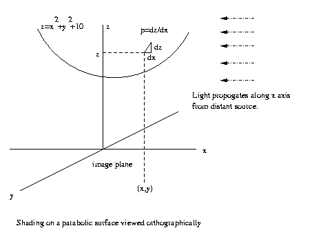
Shape-from-shading
The basic idea of shape-from-shading is that
variations in the brightness of nearby points in a
scene can usually be ascribed to variations of the
orientation of the surface with respect to the
light
source.
Eg:
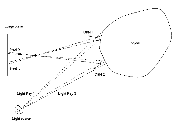
CSE668 Sp2011 03-09
the same, the total radiant energy striking the
object is the same. But that energy is spread out
over a larger surface patch for Ray 1, since the
angle between the outward pointing normal and a
vector pointing back at the light source is larger
than for Ray 2. So if this radiant energy
is reflected off the surface and captured by two
pixels of equal size on the image plane, pixel 1
will see a surface patch with lower energy density
striking it and so pixel 2 will be brighter.
CSE668 Sp2011 03-09a
From the brightness variation we can deduce that
the OPN of the surface patch imaged at pixel 2
points back at the light source, while the normal
at pixel 1, appearing less bright, must "look away"
from
the light source.
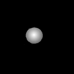
Eg: Sphere with
light source at camera.
CSE668 Sp2011 03-10
Radiometry
and
Photometry
Radiometry deals with the measurement of flows of
radiant energy (eg. visible light, RF, UV) and
photometry deals with how the human eye interprets
visible
light.
The detailed study of brightness and color
variations in an image and how they are related to
objects in the scene, their shapes, locations and
surface characteristics, the scene illumination, and
the properties of the focal plane array requires
careful radiometric modelling. Here we can only
summarize these considerations as they pertain to
the
problem
of
shape-from-shading.
We will not consider photometry at all. That is
essential for understanding how humans do
shape-from-shading, but our goal is to understand
the general process.
CSE668 Sp2011 03-11
Some
radiometric
quantities
and
their
definitions
Radiometry is concerned with how radiant energy is
emitted from a source, distributes itself in space,
is scattered by material objects, is redistributed
after scattering, then strikes and stimulates a
detector
surface.
1. Radiant flux (Phi) is the amount of power
radiated by a source. Units: Watts (W). Radiant
energy is is the time- integral of radiant flux.
Units:
Joules (J).
2. Solid angle (theta) subtended by a 3-D ray can
be measured by surrounding the source of the ray
with a unit sphere, then measuring the surface area
which
is subtended
by the ray, ie. the area of the
intersection of
the surface and the ray. Units:
steradians
(sr).
3. Radiance (L) is the radiant flux from an
emitting surface per unit surface area and per unit
solid angle. Units: W m-2 sr-1.
CSE668 Sp2011 03-12
Eg: A sphere with total surface area of 1 mm2
radiates a radiant flux of 10 W. Then if the
flux is uniformly distributed, this source
produces a radiance of
L
=
(10
W)/((10-6
m2)(4 pi sr))= 795.8 kW m-2 sr-1
4.
Irradiance (E) is
the power (radiant flux) per unit
surface
area
that
strikes
a
surface
in the presence
of
radiant
energy.
So a radiant source "throws" a spatial distribution
of radiance L(x,y,z) out into the scene. The source
might be a lightbulb, or it might be a reflecting
surface. A detector "catches" some amount of this
radiance at the point (u,v) on the image plane as
irradiance E. The brightness of the pixel at (u,v)
depends
upon E. Note that for a given radiance L at
a point
(x,y,z), the irradiance of a surface point
there will
depend on its angle relative to the
direction of
the radiant ray.
CSE668 Sp2011 03-13
Eg:
Our
lightsource
in
the
previous example
illuminates a 1 cm x 1 cm film located 5m away.
What is the irradiance on the film?
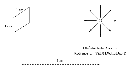
The source produces 795.8*103*10-6 = 0.795 W/sr-1.
The 1cm x 1cm film located 5m away subtends a
solid
angle
of
approximately
theta/(4*pi)
=
10-4 m2 / (4*pi*52
m2) = 4.0 mu-sr
So
the
film
will
"catch"
0.795
W/sr
*
4.0
micro-sr
= 3.18 microW
of radiant power. Then dividing by surface area,
the
irradiance
is
E
=
3.18
microW
/
10-4 m2 = 31.8 mW/m2
CSE668 Sp2011 03-14
Note that if the film were oriented at an angle of
say 45o with respect to the radiant ray, then the
solid angle subtended by the film at the source
drops by a factor of cos45o, and so the irradiance
will be reduced to .707 times the calculated value
above.
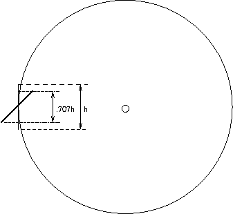
This figure is a crossection showing
that the film patch
height
on
a
sphere
surrounding the source will be reduced
by factor of 0.707 when tipped 45o. Thus the solid angle
subtended by the
film when viewed at the source is decreased
by the same factor.
For this 45o-"tipped" film surface, its irradiance is
now
E
=
0.707*31.8
mW/m2 = 22.5 mW/m2
CSE668 Sp2011 03-14a
The power which is reflected from a surface per
unit surface area into a given solid angle depends
on several factors: the irradiance at the surface,
the surface orientation relative to the ray carrying
that irradiance towards the surface, and the surface
characteristics.
CSE668 Sp2011 03-15
Surface
orientation
For each point (x,y) in the image, let z(x,y)
specify the z-coord of the surface point in the
scene visible at (x,y) in camera coordinates.
Then let us define the surface gradient vector
[p
q]T as the vector of partial derivatives
[p
q]T = [ dz/dx dz/dy]T
The 3-D vectors [1 0 p]T and [0 1 q]T, in the xz
and yz planes respectively, point tangent to the
surface, hence a vector perpendicular to both
must be a normal to the surface. One such is
the vector cross-product of these two vectors
[-p -q 1]T. (p,q) is called gradient space, and
gradient
space specifies the surface orientation.
CSE668 Sp2011 03-15a
Surface
characteristics
Surfaces reflect a specific fraction of their
irradiance, called the albedo. That irradiance
equals the reflected radiance distributed through
a 2*pi solid angle centered about the surface
normal.
If the reflected radiance is uniform in that
solid angle, the surface is said to be Lambertian,
and
the reflectance (reflected radiance) satisfies
R
=
rho*cos(Theta_i)/pi
where Theta_i is the angle of incidence (angle
between the normal and the incoming irradiance
ray) and rho is the albedo.
CSE668 Sp2011 03-15b
In general, R depends on rho, cos(Theta_i) and on the
difference between the angle of incidence and the
angle whose R is being computed (angle of
reflection or view angle). The angle of reflection
does
not matter only for pure Lambertian surfaces
with no
specular component. This is the only case we
will consider
here, the equation for R gets complicated
fast when the
specular component is considered also.
CSE668 Sp2011 03-16
Specular
vs.
Lambertian
A pure specular surface is one whose reflectance R
is zero except for that angle of reflection
equal to the angle of incidence. Such surfaces
have a "mirror" or shiny quality. Lambertian
surfaces, on the other hand, have a matte or
dull
surface
luster.
Pure specular and pure Lambertian surfaces are
just limiting cases. Real surfaces in general
have reflectance functions R which are neither
uniform
nor
non-zero
in
just
one
direction.
CSE668 Sp2011 03-16a
Image
irradiance equation
The basic radiometric conservation equation is that
which says the irradiance E "caught" at a point
(x,y) on the image plane equals the radiance R
"thrown" at that point from the corresponding
object point which is being imaged. In simplest
form
(see Sonka p 493-494, Trucco p 223-224)
E(x,y)
= R(p(x,y),q(x,y)) = R(dz/dx,dz/dy)
where z=z(x,y) is the depth of the surface point.
CSE668 Sp2011 03-16b
This
form of the irradiance equation assumes,
among other things, that the radiance function
depends only on surface orientation (Lambertian
assumption), that the light sources and
image plane are distant from the scene, and so
perspective projection is well characterized by
orthographic projection, ie. image coordinates
(u,v) equal the camera coordinates (x,y).
CSE668 Sp2011 03-17
Eg:
Orthographic projection means that the image is
projected onto the x-y image plane in the "usual"
way we think of
projection of a 3D point onto a
2D plane,
[x y z] -> [x y 0]. Note that using
orthographic
projection, the image plane location
[u v]T
= [x y]T does not depend on z. With perspective
projection,as
in our pinhole model, the projection of
an object point
[x y z] into the image plane depends not
just on x and y, but z as well.
CSE668 Sp2011 03-18
Then continuing with the present example, for each point
on the surface of the parabaloid,
z(x,y)
=
x2+y2+10
p(x,y)
=
dz/dx = 2x; q(x,y) = dz/dy
=
2y.
Lets determine R(p(x,y),q(x,y)). Assuming Lambertian
surface, R = cos Theta_i/pi where Theta_i is the
angle
between the surface normal and source ray.
n = [-p -q 1]T = [-2x -2y 1]T
But
the cosine of the angle between a pair of vectors
equals their inner product divided by the product of
their norms, so
cos
Theta_i
=
[-2x
-2y
1][1 0 0]T
-------------------
|[-2x
-2y
1]|*|[1
0
0]|
CSE668 Sp2011 03-19
and the
irradiance equation becomes
E(x,y)
=
2x
-----------------
pi*(4x2+4y2+1)1/2
Thus for instance, the brightness E on the image
plane would be zero along the y-axis (why?) and
go
asymptotically to its max for large x (why?).
CSE668 Sp2011 03-20
Solving the IIE E(x,y)=I(p,q) for p(x,y) and q(x,y)
Given
the radiance E(x,y) over
an image, the image
irradiance
equation
E(x,y)=R(p(x,y),q(x,y)) can be
used to
determine
(or estimate) p(x,y) and q(x,y).
If you
know the orientation of the tangent plane
to the
surface everywhere, you know the shape.
There are two
classes of methods used for solving
the IIE, which
is a partial differential equation. The
Characteristic
strip method is a classical pde-solver,
while the
optimization method works on the priniciple
of finding a
function which is a good global fit to the
data.
CSE668 Sp2011 03-20a
Characteristic
strip method:
Starting from a point (x,y) where z, p and q are
known,
pick a path l and solve
dx/dl= Rp, dy/dl=Rq, dz/dl=pRp+qRq
dp/dl=Ex, dq/dl=Ey
Known points include occluding boundary and max / min
points of brightness, where patch orientation is
perpendicular to / parallel to light ray.
CSE668 Sp2011 03-21
Optimization
method:
Given the Irradiance map E(x,y), an given the
Reflectance map R(p,q) (but not knowing
the (p,q) values as functions of (x,y)), find
the functions p(x,y) and q(x,y) which minimize
the sum over
the entire
image of the energy fn
[E(x,y)-R(p,q)]2+ λ[(del2p)2+(del2q)2]
Here del2() is the Laplacian operator (sum of squares
of the partials
with respect to x and y). It is a
frequently-used
measure of the irregularity of a fn.
This minimization is a
variational calculus problem
which can be
solved via
relaxation methods.
CSE668 Sp2011 03-22
Once
p(x,y)
and
q(x,y)
are
known over the entire
image, since the surface gradient is defined by
[p q]T = [dz/dx dz/dy]T
then taking a single fixed depth reference point
(xo,yo,1) we can integrate outward over the image
from that point
to recover normalized z(x,y).
CSE668 Sp2011 03-23
Now what can we
say about the effectiveness of the
shape-from-shading algorithms? The problem is
in general ill-posed, ie. has more degrees of freedom
than constraints induced by shading of the image.
Ill-posed problems can be regularized by addition
of hard constraints, for instance limiting the
surface chacteristics or the types of objects
being imaged (blocks-world approach) and/or by
addition of soft constraints (optimization
approach using
irregularity as soft constraint).
Problem is whether the regularized problem becomes
artificially
overconstrained.
CSE668 Sp2011 03-24
Other shape-from algorithms
Stereo and shading are not the only cues that can
be used to infer local surface orientation and
depth
distribution.
Shape-from-texture
Consider the following image:
It is hard to avoid the perception that the
surface shown tips down to the left and
forward. Why do
we have that perception?
CSE668 Sp2011 03-25
A texel is the basic repeating pattern of a 2-D
texture. A texture is any 2-D periodic
image or
portion of an
image.
Eg: In the binary image
000010000100001000010000100001000010000100001
100101001010010100101001010010100101001010010
000010000100001000010000100001000010000100001
100101001010010100101001010010100101001010010
000010000100001000010000100001000010000100001
100101001010010100101001010010100101001010010
.....
the texel is
00100
01010
The texture
has 2-D periodicity (2,5).
Note that the
texel for a given perodic image is defined
only up to
arbitrary horizontal and vertical phases.
Eg (cont;d): shifting the horizontal phase by 2 pixels, the
texel
for
the
previous
example can be written 10000
01001
or
shifting
horizontal
phase
by
2 and vertical phase by
1,
can
also
be
written
01001
10000.
CSE668 Sp2011 03-26
The eye tends to assume that once a texel has been
identified, distortions to its shape are due to
changes in the surface orientation of the surface,
or due to
perspective projection.
Eg: Suppose we have identified a texel as a
square. but at one point in the images,
one of these texels looks like a trapezoid
in perspective projection. We can infer the
plane of the surface normal.
CSE668 Sp2011 03-27
Eg: A square mesh distorted by the shape of
a function into a "wire-mesh 3-D
graph."
The
function
is
the
sinc fn
z(x,y)=sin(d(x,y))/d(x,y)
where
d(x,y) = sqrt(x^2+y^2)
CSE668 Sp2011 03-28
Shape-from-texture algorithms work by determining
the undistorted texel shape, then matching each
texel in the image to that shape modified by a
distortion function which reveals the surface
orientation. It can be done discretely, texel by
texel, or continuously, computing rate of change
of surface
gradient vector.
Eg: A square texel would look like one of the
texels two images ago if its surface normal
was
approximately
[1
1
-1]T.
Sonka does not give any actual algorithms, see
Trucco STAT-SHAPE_FROM_TEXTURE p. 240-241 for
one such.
CSE668 Sp2011 03-29
Shape-from-photometric-stereo
For a
Lambertian surface and using orthographic projection,
we showed that
R
=
rho
(cos
Theta_i
/ pi)
where rho was the albedo, and Theta_i the angle
between light
source and surface normal. Rewrite as
R
=
rho
(L*n)
where L is a vector whose direction is that of the
light ray and magnitude is the strength of the
irradiance, and n is the unit surface normal
vector. Note
the factor of 1/pi is subsumed in L.
CSE668 Sp2011 03-30
For a single fixed surface point (x,y) suppose we
take 3 images
with three different L-vectors, ie.
using three
different lighting conditions:
E1(x,y)
=
rho
(L1*n)
E2(x,y)
=
rho
(L2*n)
E3(x,y)
=
rho
(L3*n)
Here Ei are the three measured irradiances at the
same point (x,y) in the image plane under the three
different lighting conditions. Then we can re-form
these 3 scalar
equations into a single vector-matrix
equation
E/rho
=
L*n
where E = [E1 E2 E3]T, and the 3x3 matrix L has
L1, L2 and L3
as its
rows. Then
n
=
(1/rho)*L-1*E
CSE668 Sp2011 03-31
This is shape-from-photometric stereo. Note that
if >3 images are available, can use least squares
fit to
overdefined equations (more robust).
Limitations
with
s-f-p-s as presente here is the
perfect
Lambertian assumption and the use of
orthographic
projection.
Gets a
lot more complicated
without those
idealizations.
Another concern: not very biomimetic, ie. doesn't
relate to any
evolutionary mechanism.
CSE668 Sp2011 03-31
Shape-from-motion
If we watch an object go around a merry-go-round,
we can perceive its 3-D shape from the many views
of it which we see. Similarly, if we walk around a
statue, we can recover its shape. This is
shape-from-multiple-views,
or
shape-from-motion.
The key tool
here is the Structure from motion theorem.
Structure from
motion theorem: given 4 or more
non-co-planar points on a rigid body as viewed
in 3 or more non-co-planar orthographic
projections, the 3-D displacements between the
points may be
determined.
CSE668 Sp2011 03-32
Proof of the theorem involves only projective
geometry, and proceeds by selecting one of the
points as the origin, finding the translation
of that point between images and the rotation
of the rigid body around that point (see Sonka
p. 510-512).
One difficulty with shape-from-motion is separ-
ating shape parameters from motion parameters.
Another is the rigid body assumption. For
instance, cars are rigid bodies but tractor
trailer trucks
are not. People are not.
CSE668 Sp2011 03-33
Shape-from-motion can also be approached on the
continuous level from optical flow, ie. the
movement in image space of grey levels. We will
develop optical flow in the next section of this
course, on
motion analysis.
Other shape-from concepts discussed in Sonka
include shape-from-focus/defocus and shape-
from-contour. These are perhaps less important
than shape-from-X where X={stereo, shading,
texture, photometric stereo, motion}. In nature
all these, with the exception of X = photometric
stereo, have been shown to be important shape
determination mechanisms.
CSE668 Sp2011 03-34
Summary
remarks about shape-from methods:
1. Shape-from-stereo is a practical tool in
many
realistic
settings.
2. Shape-from-shading works well only in
structured
and
well-characterized
settings.
3. Other shape-from methods are of limited
practical value in current practice, work
only
for
a
narrow
range
of applications.
4. What is missing from these methods is the
notion of goal-seeking behavior, view
planning.
We
will
explore
that
shortly.
CSE668 Sp2011 03-35